Properties Dialog
When placing supports, a common Properties dialog is used to define various properties for the selected support component. While the fields in the dialog may differ according to the type of component being placed, how the properties are defined remain basically the same.
The dialog consists of different property sections, which can be displayed or collapsed by clicking the arrow icon to the far right of the section header.
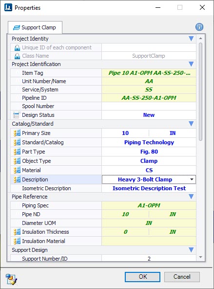
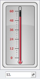
The Properties dialog provides numerous ways to define the various property values for a component. Some fields are defined by typing a value in directly, while others provide a drop down list of available value to select from. Other fields may have some sort of control for defining a value such as the Operation Temperature field which displays the following control allowing you to use the thermometer's sliding scale to adjust the temperature setting. The current value is displayed in the field below it, where the value can also be entered manually.
When you click in one of the Catalog fields, the following grid displays database information on the available component types.
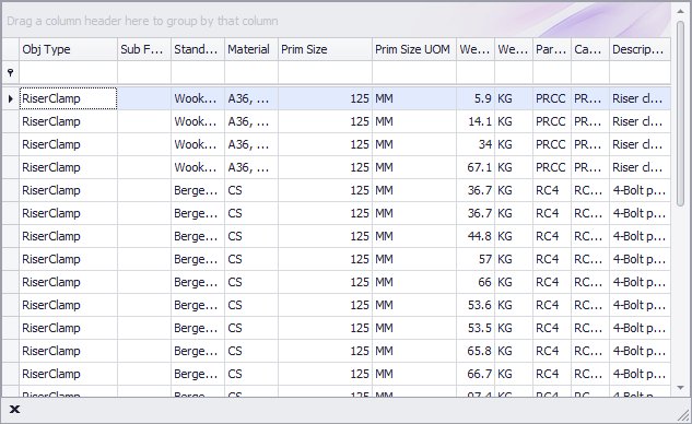
This grid display all of the catalog records for the type of component you selected to place.
The columns in the grid can be expanded for a better view of the headers and the values within.
Select a record from the grid to apply its values in the Component Placement dialog. When a record is selected, the default preset values are applied to the Component Placement dialog where required.
The resulting new values are displayed in Blue in the dialog as shown:
When you have finished defining the component's properties, click OK to continue with the placement procedure.
Setting Default Catalog Entries
When selecting a catalog entry from the grid display, there is an option that can be defined in the Project Dashboard which will use the first catalog record as the default size when placing a support:
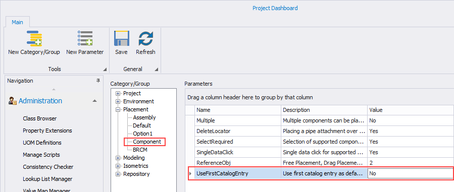
- No (Default): User will be prompted to pick a catalog record for each placement.
- Yes: Setting this parameter to Yes will query the catalog using the selected pipe or structure size and set the first catalog record which matches this criteria as the default. For assemblies, it will use this query to return default sizes for each component in the assembly.
Isometric Description
The Isometric Description field lets you define a unique description which will be displayed for the component when running an isometric.
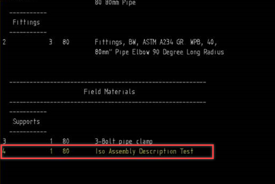
If no Isometric Description is defined then the standard component description will be used.
Filter the Component Grid
Each header has a drop down filter list allowing you to filter the grid according to the selected filter value. For instance, the following filter list is displayed from the Standard (Catalog) column:
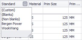
If you select Bergen Power from the list, then only components from the Bergen Power catalog will display.
If you click the Custom option, it will display the Custom Auto Filter Dialog allowing you to create a custom filter for the grid.
Placing Assemblies
When you place an assembly, you must first select the type of assembly from the Select Assembly dialog. Once the type of assembly has been decided, you will need to define the property values for each component included in the assembly. The Properties dialog displays a tab for each assembly component as shown below:

Define the properties for each assembly component. Once the properties have been defined on one component, click OK to proceed to the next tabbed section.
If you click the arrow icon in Assembly field the Assembly Definition dialog displays, which lets you save the assembly and its property values to the project database.
When the property values for all of the assembly components have been defined, click OK to place the assembly in the drawing.